
Background
My fav supplier, All Electronics, had this Hella relay listed at an attractive price. But no specs or other info and scant data on the web either. Hmmm. Curiosity got the better. I purchased a few and, caution to the wind, cut one open for a quick peek inside.
The 7 pins were a puzzle. No markings on the relay to tell what went where. Google to the rescue? I did find an electric fuel pump relay by Hella for an Opel Vauxhall using the exact same pin layout. Nothing else came close. But clearly this wasn't a fuel pump relay. I chose to apply the terminal designations from the Vauxhall relay to this mystery relay, even though the numbers don't jibe with automotive standards in this circuit. The original application for our relay no doubt used an entirely different numbering scheme; just so you are aware...
Applying 12V power to the various pins (carefully) didn't produce any meaningful results so it looked like tracing the circuit was the next step. Excessive? Yes, probably. But a good challenge nonetheless.
Probing all those board components with an Ohmmeter just added to the confusion; it was time for a more organized approach.
A scan of the copper traces with component designations attached.
 A
A
And a photo of the component side of the board:
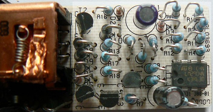
This turned out to be quite helpful. Little by little the circuit began to appear and is shown below:
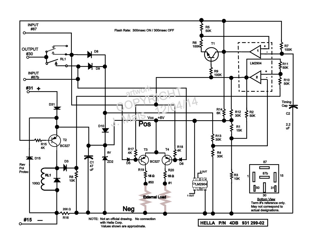
It does indeed appear to be a flasher relay, but not an
ordinary one. Here's a quick overview of the circuit as I see it:
12V Battery is applied to Terminals #15 (Neg)
and #31 (Pos). That charges capacitor C1 to roughly 8V thru diode D31 (my
numbering) and dropping resistor R16 (200 ohm). D31 also supplies
full 12V to the relay RL1.
8V is also supplied to the LM2094 dual op-amp which performs the timing functions. Under these conditions, the op-amp begins the flashing sequence but not much else happens.
Output transistors T3 and T4 are the key. They are intended to flash some external load, such as a small indicator. I expect that 100 ma would be the limit and no inductive components, please. These 2 PNP devices are fed +8V on the emitters and R17 and R18 bias the bases in tune with the flash sequence. But there are also diodes D5 and D6 to contend with. They have the capacity to drive the base level higher than emitter voltage (by a fraction of a volt), thus cutting off the transistor. This can only happen if 12V is applied to Terminal #87 or #87b. These inputs are somewhat sensitive and 12V applied thru as much as a 100 ohm resistance will do the job. The fraction of a volt positive bias occurs due to the voltage drop across diodes D10 and either D8 or D9.
If 12V is applied to Terminal #87, diode D5 cuts off T3. If 12V is applied to #87b, then diode D6 cuts off T4. In the meantime, the flasher circuit is pulsing relay RL1. Each time that the relay energizes, Terminal #30 goes to 12V, fed from either #87 or #87b. More importantly, #87b goes to 12V (if #87 is held at 12V) each time the relay closes. This has the effect of switching T4 off and on at the flash rate. Exactly the opposite occurs if #87b is held at 12V: T3 switches off and on at the flash rate.
I have seen references to flashers like this one which were used for trailer lighting and the 2 transistor outputs were intended for pilot signals called C and C1.
It's possible that Terminal #30 is an Input, perhaps from the Hazard switch, and that the relay then flashes both outputs #87 and #87b.
#31 may be from the Ignition switch (and would more properly be labeled #15).
That's all the info I have. Maybe someone will recognize the relay and be able to add something new.
Let me state again that the terminal numbers I have shown are most likely not the correct designations for this relay; they don't correspond to accepted practice and are only presented for reference.
This Web Page Created with PageBreeze Free HTML Editor